Service Controller Altai is based on the same firmware version as Mikrotik devices. Both devices use RouterOS system. The settings of the Altai Service Controller 1600 is based on the same setup guide as for the standard Mikrotik. There is only one difference: Altai Service Controller has a serial number which SOCIFI uses for the device identification. For the identification of the device the mac address of the first ethernet device has to be used
For the fast settings, we described the main important steps in this guide.
1) Time synchronization - Setting SNTP client
The first step is a configuration of time synchronization. It is configured in the SNTP client (time) on the menu:
System > SNTP Client
Enabled: Checked
Mode: Unicast
Primary NTP Server: 0.north-america.pool.ntp.org (for example)
Secondary NTP Server: 1.north-america.pool.ntp.org (for example)
| Info |
|---|
Please set servers that are as close to your location as possible. You can find NTP list here: http://www.pool.ntp.org/en/ |
sntp.jpg?version=1&modificationDate=1487940840698&cacheVersion=1&api=v2)
sntp.jpg?version=1&modificationDate=1487940841027&cacheVersion=1&api=v2)
Enable the correct time zone System > Clock > Time Zone Name:
America/Montreal (or according to your location):
sntp.jpg?version=1&modificationDate=1487940841362&cacheVersion=1&api=v2)
The time is automatically synchronized after the correct termination of LAN configuration.
2) Radius settings
The second step is a configuration of a client for the external SOCIFI RADIUS server. It is necessary for authentication and managing parameters of clients connections. Here are necessary to be enabled the communication from the Altai Service Controller to the SOCIFI RADIUS servers for the UDP packets on the standard radius ports (1812/udp and 1813/udp). This must be enabled on each device in the way between controller device and the SOCIFI RADIUS server
| Anchor | ||||
|---|---|---|---|---|
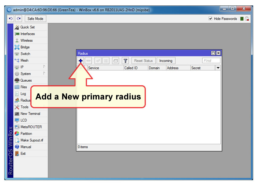
|
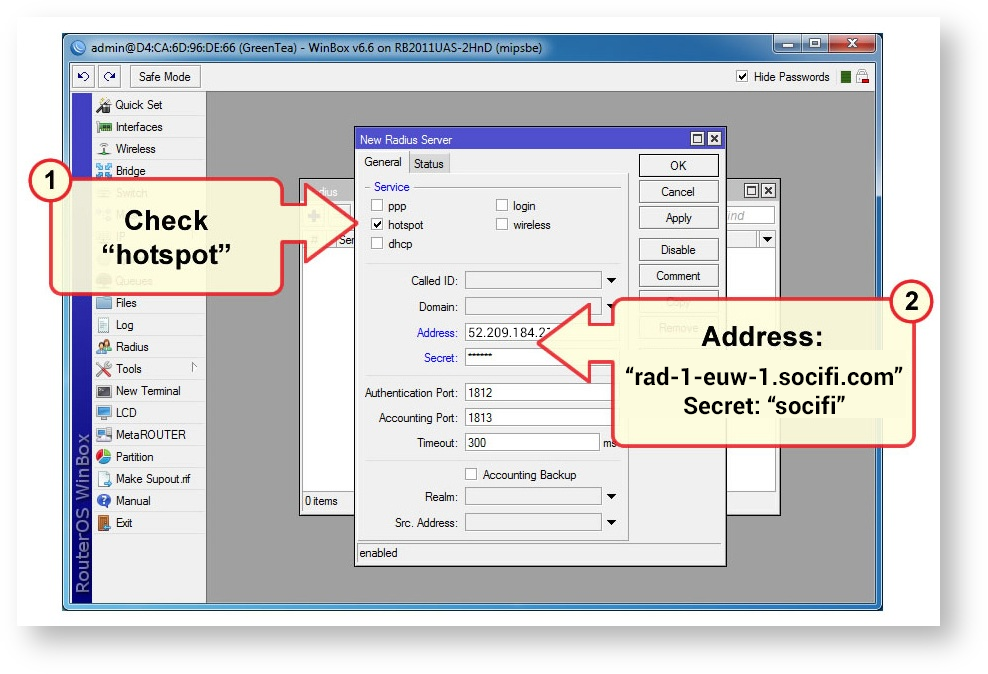
Add primary radius server (RADIUS Server 1):
Radius + General tab
Servis
hotspot: checked
Called ID :
Domain:
Address: rad-1-euw-1.socifi.com (for example)
| Include Page | ||||
|---|---|---|---|---|
|
Secret: socifi
Authentication port: 1812
Accounting port: 1813
Timeout: 300 ms
Accounting Backup: unchecked
Src. Address:
Add secondary radius server (RADIUS Server 2):
Radius + General tab
Servis
hotspot: checked
Called ID :
Domain:
Address: (for example)
Secret: socifi
Authentication port: 1812
Accounting port: 1813
Timeout: 300 ms
Accounting Backup: unchecked
Src. Address:

3) Bridge settings
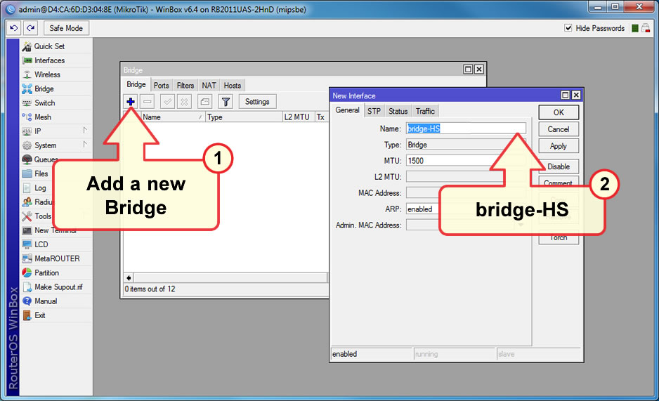
As the third step must be created a new bridge interface. This new bridge interface will be used as the virtual input interface for the SOCIFI hotspots system.
Bridge > Bridge tab > +
New Interface: General tab
Name:bridge-HS
OK
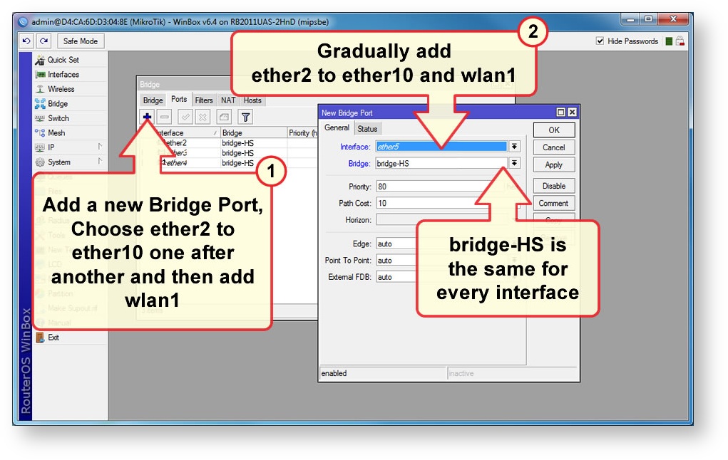
For the connection between the new bridge interface and some physical input interface with data for SOCIFI platform, must be added this physical interface to the new bridge interface. For example, physical ether2 interface will be added to the new bridge interface:
Bridge > Ports tab > +
New Bridge Port: General tab
Interface: ether2
all on Bridge:bridge-HS
| Info |
|---|
When it used some VLAN for SOCIFI data from input devices then must be added this VLAN interface to the new bridge. |
4) Hotspot settings by wizard
In this step will be created the main hotspot system using the inbuilt Hotspot Wizard
Definition of the SOCIFI hotspot
Run the definition of hotspot:
IP > Hotspot > Servers Tab, Hotspot Setup
...
The number of IP addresses should submit their license (L4 = 200 addresses). See notes at the end of the manual.
| Warning |
|---|
If you are customer with White Label solution, please change your custom domain from hotspot.socifi.com to your custom domain (for example mycustomdomain.com) at step 7 |
Hotspot Setup:
- HotSpot Interface: bridge-HS
- Local Address of Network: 10.50.5.1/24
- Address Pool of Network: 10.50.5.2 - 10.50.5.254
- Select Certificate: none
- IP Address of SMTP Server: 0.0.0.0
- DNS Servers: 10.50.5.1 / 8.8.4.4 / 4.4.4.4 (or will be better using our DNS servers from your site or your provider)
First DNS server address must be the interface address!! - DNS Name: hotspot.socifi.com (required)
This domain could be adjusted to fit your needs. For example hotspot.mydomain.com - Name of Local HotSpot User: user

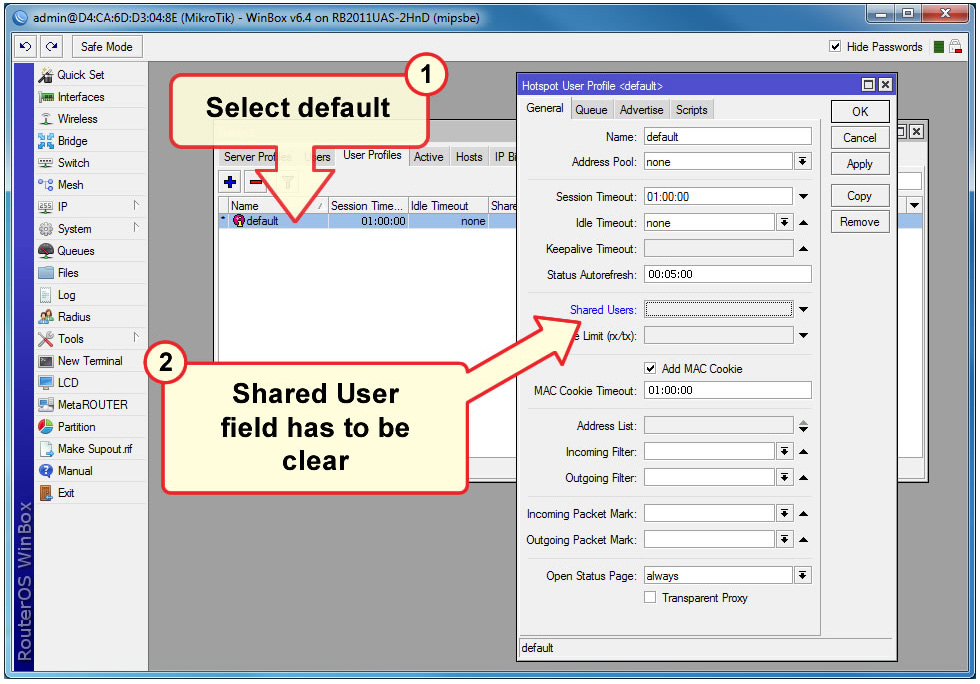
The changes in the Hotspot settings
Remove Shared User (default = 1):
IP > Hotspot > User ProfilesDefault , General Tab
Shared Users: clear
OK
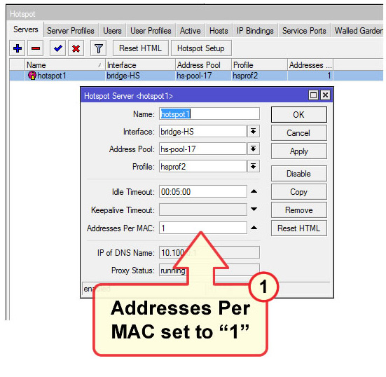
Addresses per MAC = 1 (default = 2 )
...
Change the Name from the default value of hotspot1 to value "AL_ <mac_address_of_first_ethernet_interface>", for example "AL_3F0602DFA144".
OK
Change the method of the Authentication:
IP > Hotspot > Server Profiles select hsprof1
Hotspot Server Profile <hsprof1> Login Tab
HTTP PAP: checked

Use RADIUS: Checked
Default Domain:
Location ID:
Location Name:
Mac Format: XX:XX:XX:XX:XX:XX
Accounting: Checked
Interim-Update: 00:01:00
Nas Port Type: 19 (wireless-802.11)

5) Scripts WalledGarden and ReplaceLogin
In this step will be made some changes in the configuration by the inbuilt scripting system
...
Create WalledGarden script: System > Scripts +
Name: WalledGarden
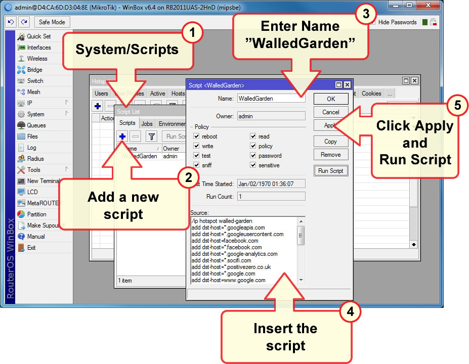
Copy & paste following script:
Include Page Mikrotik Mikrotik
The result is a list of servers:

| Info |
|---|
The list of Walled Garden servers is changed from time to time, you may be asked to change its contents. The current list is always in this documentation. Before you run the script again (even if with new content), first you must delete old Walled Garden server list (otherwise the list would be permanently duplicated). |
Creating a definition for hotspot login
Script definition for content of hotspot / login.html
We generate a hotspot / login.html file the same way: System > Scripts > +
Name: ReplaceLogin
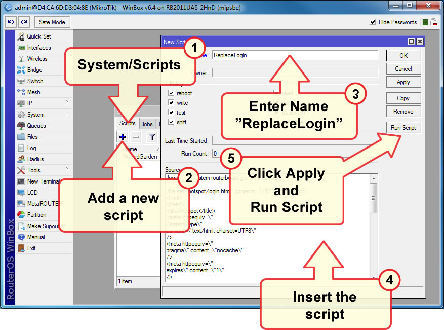
Click Apply and then run script: Run Script (change takes the effect by changing the date and time of the file: File hotspot/login.html). Copy & paste following script:
| Warning |
|---|
If you are customer with White Label solution, please change http://connect.socifi.com to your custom domain (for example http://connect.mycustomdomain.com) |
| Warning |
|---|
Some RouterOS devices have default storage on the flash memory. In this case it is necessary to modify part of this script “/file” in according to its actual storage name, e.g.: "/file set flash/hotspot/login.html contents=" supposing that link "flash/hotspot/login.html" exists. It is necessary to check it in the list of files in the "File" module. |
| Code Block |
|---|
:set mac [interface ethernet get ether1 mac-address]; /file set "hotspot/login.html" contents="<html> <head> <meta http-equiv=\"refresh\" content=\"0; url=http://connect.socifi.com/?rad=yes&serial=$mac&client_mac=\$(mac)&client_ip=\$(ip)&userurl=\$(link-orig)&login_url=\$(link-login-only)\" /> <meta http-equiv=\"pragma\" content=\"no-cache\"> <meta http-equiv=\"expires\" content=\"-1\"> </head> </html>" |
6) Connecting your MikroTik to SOCIFI Dashboard
When adding Altai device you'll need to use the MAC address of the first ethernet ports as was described in chapter 4
...
| Include Page | ||||
|---|---|---|---|---|
|
...And on of the end some important things in settings where users make some error:
- the name of the hotspot - "AL_<mac_of_the_first_etherent_interface>" in IP > Hotspot > Server menu
- time synchronization
- the correct settings of the input interface to the hotspot input bridge interface
- WalledGarden - sometimes is error that is used WhiteLabel domain and not add it to the WalledGarden
- ReplaceLogin script - checking when was the file "login.html" replaced